7-Segment Digit Display via HDMI
A project that converts quadrature encoder input into a large, dynamic 7-segment style digit displayed on an HDMI monitor, illustrating FPGA-based graphics generation.
The 7-Segment Digit Display via HDMI project demonstrates how to use FPGA logic to take quadrature encoder signals, convert them into a count, and then display a corresponding hexadecimal digit as a large, pixel-based 7-segment figure on an HDMI screen. This blend of digital signal processing, timing generation, and video output highlights an integrated FPGA design flow.


Key Features of the Project:
-
Quadrature Encoder Interface:
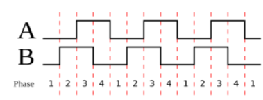
Interprets A/B signals from a rotational input device to maintain a count. Rotating the encoder forwards or backwards increments or decrements the count respectively. -
Hexadecimal Digit Rendering:
Extracts the lowest 4 bits of the count and maps it to a 7-segment pattern (0–F). This digit is scaled up and drawn as a large pixel-based figure, making it easily visible on a monitor. -
VGA Timing and HDMI Conversion:
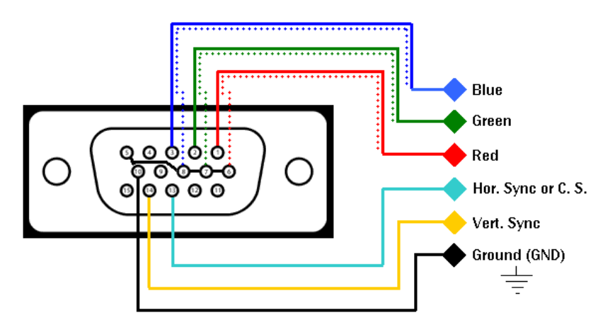
Uses a VGA timing generator (vga_sync) to produce horizontal/vertical sync signals and pixel coordinates. These signals, along with RGB pixel data, are passed to an HDMI transmitter IP core to output digital video on an HDMI-compatible display. -
High-Level Integration:
Combines clock generation (via a clock wizard), quadrature decoding, VGA timing, pixel computation, and HDMI output into a single cohesive FPGA design.


Detailed Steps:
-
Quadrature Encoder Processing:
TheQuadratureEncodermodule synchronizes and interprets A and B signals, determining rotation direction and updating the count register accordingly. A well-defined state machine ensures robust detection of forward/backward steps. -
Hex Digit to 7-Segment Pattern:
The count’s lower nibble selects one of 16 hex values (0–F). A combinational logic block translates this value into a 7-segment configuration (segments), where each bit represents a segment line (a–g). -
Pixel-Based Rendering:
Using the VGA pixel coordinates (px,py), the design checks if the current pixel falls within one of the “segments” that define the large digit’s shape. If yes, that pixel is lit (white), otherwise it’s black. This forms a giant on-screen “LED segment” effect. -
Clocking and HDMI Output:
A clock wizard IP provides a stable 25 MHz pixel clock and a 125 MHz 5x clock for HDMI. Thevga_syncmodule generates standard 640x480 VGA timing. Thehdmi_tx_0IP then encapsulates the RGB signals and syncs into HDMI format, ready for display on a standard monitor.
Project Advantages:
-
Visual Feedback:
The large 7-segment digit offers immediate feedback on encoder position, making it easy to understand and debug rotational inputs. -
Scalability:
The logic can be extended to display multiple digits, more complex graphics, or integrate with other peripherals (e.g., buttons, sensors). -
Integration of Multiple Domains:
The project shows how FPGAs handle both simple digital logic (incrementing a count) and more complex tasks like generating video signals. This demonstrates the FPGA’s versatility.

Technologies and Tools:
- HDL (Verilog/VHDL): For writing the QuadratureEncoder, 7-segment logic, and top-level integration code.
- Vivado (Xilinx): Used for synthesis, implementation, and bitstream generation for the FPGA.
- HDMI IP Cores and Clock Wizard: Pre-verified IP cores facilitate quick and reliable generation of video signals and stable clocks.
- Real-Time Testing: Rotating the encoder updates the displayed digit, offering a direct real-time demonstration of the FPGA’s capabilities.
Conclusion: This project merges low-level hardware control (encoders), mid-level logic (7-segment decoding), and high-level video output (HDMI). The result is a visually clear and interactively changing display, exemplifying how FPGAs can bridge digital inputs and complex video standards to create intuitive and dynamic user interfaces.
Future Enhancements:
- Display multiple digits to show entire counts or metrics.
- Integrate color changes or animations to enhance readability or aesthetics.
- Combine with other inputs (e.g., temperature sensors) to display measured values.
By expanding on these foundations, even more sophisticated FPGA-based HMI (Human-Machine Interface) solutions can be created, paving the way for innovative control panels and embedded display systems.